|
|
Post by wbill76 on Jan 12, 2014 12:44:54 GMT -5
Continuing on with the construction phases, I worked on Step 8 which deals with the propeller and hub assembly. The blades are separate from the two part hub and are nicely molded and the prop shaft has a notch that lines up with the opening inside the spinner cap. This, combined with how the base of the spinner and the tank that attaches to its back all line up mean that the prop can't rotate once everything is installed, so I had to decide how I wanted the prop to align first before committing to glue.  The little side notches on the tank behind the spinner align with tabs on the inside of the fuselage halves to keep everything lined up properly. Currently the prop and spinner are only dry fit together to make it a little easier to paint the prop later on before installing it permanently into the spinner.  Moving on to Step 9 which deals with the wings, I installed the radiator parts along with their covers/speed flaps. The radiators were painted with MM non-buffing Metalizer and the inside areas of the covers/flaps with MM RLM 02.  Since I wasn't fitting the under-wing gun pods, I skipped the optional parts that support that and added the upper wing halves. The fit here was very good, rather than use rubber bands I opted for smooth jaw clamps placed at strategic points to ensure the glue set evenly with both halves.  While that was setting up, I assembled the two-part elements for the flaps and ailerons and cleaned up the leading-edge slats. In order to position the flaps at the correct dropped angle, I removed the little mount tabs they had on their front edges and carefully glued them into position with liquid glue and used a metal ruler to gauge the correct angle/gap on both sides so they matched up with each other. Ailerons and slats were installed as well to complete the wing assembly.  Step 10 pulls the fuselage together but I'm not quite ready for that, but I did start work on the front nose panel by drilling open the mount holes for the support posts for the air filter and installed the air intake mount as well. The intake is in two halves so careful gluing with liquid glue and a bit of sanding were needed to give it a seamless look. Last but not least for the day, I assembled the two-part components for the rudder and the horizontal stabilizers as called for in Step 11. The elevators were cleaned up and installed in the level position as well.  Next up will be finishing off some of the remaining construction odds and ends and prepping for painting on the interior before the fuselage gets joined up. |
|
|
|
Post by bbd468 on Jan 12, 2014 12:53:37 GMT -5
Lovely build Bill, so clean and crisp. More man!  |
|
|
|
Post by wing_nut on Jan 12, 2014 14:22:02 GMT -5
Looks great Bill. to bad the prop detail at the base can't be seen in the spinner like on the "E". Looks like Trumpy got the spinner profile right. They didn't get the shape of the opening for the prop though. None of the kits do, probably because it would be hard (impossible?) to get the piece out of the mold. Have the AC manufactures adopted some of the slide mold tech used by the armor guys? they could get it right with that I think. The opening has a sort of tear drop shape, slight pinch at the base. You can see it in the pic below. This is one of my fav 109 pics, I love how it shoes dark seams and rivets (do oyu think this might ignite "that" argument again  )and some cool streaking back from the seams. And Bill... check that clam shell... nudge, nudge, wink, wink! Photo used for discussions purposes only.  |
|
|
|
Post by wbill76 on Jan 12, 2014 14:52:48 GMT -5
Thanks Gary, working my way towards the inevitable AB work! Marc, I know Trumpeter used some slide molding on this kit...the underwing gun pod cannons for example have their muzzles molded hollow but Trumpeter uses it far less than Dragon for example. I suppose to keep the costs of their kits down overall more than anything else. Love that pic, it's one I've got in my reference folder as well for this project. It's the reason I asked about the clam shell!  |
|
|
|
Post by wing_nut on Jan 12, 2014 16:15:26 GMT -5
It's the reason I asked about the clam shell!  Great minds and all that rot  |
|
|
|
Post by wbill76 on Jan 12, 2014 16:18:08 GMT -5
It's the reason I asked about the clam shell!  Great minds and all that rot  Just don't expect me to suddenly start building stuff in 1/144!  |
|
|
|
Post by bullardino on Jan 12, 2014 16:18:14 GMT -5
Fantastic job, Bill. Now there's really mothing you can't do...
|
|
|
|
Post by deafpanzer on Jan 12, 2014 19:54:09 GMT -5
OMG! How did you manage to find time to model on a weekend with four great football games?!?! LOL The wings are looking good... are those clamps any good and where can I get those?
|
|
|
|
Post by wbill76 on Jan 12, 2014 20:30:26 GMT -5
Thanks Luigi! Plenty of unconquered frontiers out there, never fear.  Andy Andy, it wasn't easy...had to squeeze in time here and there to scrape together enough progress to be worth posting about. The clamps are smooth jaw copper clamps designed to work as heat sinks for soldering. They come in very handy for other uses I've found as well. I picked up a bag of them at Radio Shack a couple of years back for use in solder work but they see most of their use as plain old clamps these days. Look for them under that kind of a listing and you should be able to find them pretty easily. |
|
modelfreak72
Full Member
  
Member since: January 2012
Why worry, each of us is wearing an unlicensed nuclear accelerator on his back.
Posts: 1,479
Jan 28, 2012 23:21:46 GMT -5
Jan 28, 2012 23:21:46 GMT -5
|
Post by modelfreak72 on Jan 14, 2014 9:34:08 GMT -5
Moving right along! The wings look great! That cockpit has nice detail to it, gonna look good with the fuselage wrapped around it!
|
|
|
|
Post by wbill76 on Jan 14, 2014 12:21:14 GMT -5
Thanks MF! I'm trying to get as much of the construction/clean-up done as possible before paint starts to fly, almost there!  |
|
|
|
Post by wbill76 on Jan 17, 2014 20:37:59 GMT -5
Sometimes it amazes me how the smallest of things can often times cause the biggest headaches on a build. On this particular build, that turned out to be the case with the "Tropen" filter fitted to the large air intake on the cowling. For whatever reason Trumpeter designed the front 'clam-shell' doors on the filter to be installed only in the 'open' configuration...something that makes no sense really when you think about it especially as all the reference photos I was able to find of Trops on the ground showing it closed to, of course, allow the filtration to actually work. To get a 'closed' look on the filter front required some extensive re-working of the kit parts. As molded, they don't meet up correctly if 'closed', so I had to use a good bit of putty and sanding to reshape the front parts into something closer to what it should actually look like and fair it back in with the rest of the filter.  The issues didn't stop there however...the mount arms/pins that support the filter also had to be modified. With the doors now covering the holes that the pins would go into, the pins were trimmed off and I installed the bottom support first to get it properly lined up with the normal intake. When it came time to install the top, it became abundantly clear that the holes that the instructions called to be drilled out earlier were too high for the top bar to meet up with the filter as it should. That meant filling those holes, trimming off the pins, and moving the mount low enough (and also shortening its support arm to the right length)to match up properly with the filter.  So something that started out being just a simple installation turned into a major modification that took a couple of hours to resolve!  |
|
|
|
Post by Leon on Jan 17, 2014 20:57:59 GMT -5
Making good progress Bill.Looking really good.  |
|
|
|
Post by wbill76 on Jan 17, 2014 21:08:38 GMT -5
Thanks Leon! Tonight's little session was supposed to finish up the little details I needed to before I could start spraying paint...but that will be delayed into tomorrow a little bit due to this little side-trip issue resolution.  |
|
|
|
Post by wing_nut on Jan 17, 2014 22:51:59 GMT -5
Lots of work just to close a little clam shell. But it looks life you came out on top.
|
|
|
|
Post by bullardino on Jan 18, 2014 5:44:55 GMT -5
Nice job on that tiny part, Bill. I agree with your choice, the filter was open on the ground only to allow ground crew to work on it. Otherwise it was kept closed as the planes had to be read to takeoff in a very short time  |
|
|
|
Post by wbill76 on Jan 18, 2014 10:40:04 GMT -5
Marc, no kidding! I found it even more ironic considering Trumpeter went out of their way to provide the Tropen filter as a separate sprue for this kit to make the 'Trop' variety and then got it wrong on multiple levels!  Luigi Luigi, thanks as always! I hear you about the need for maintenance access or to replace the filter, etc. I can only guess that Trumpeter used either a museum piece showing it open as their basis or for some other reason decided to design it in the open/maintenance configuration...but to provide that as the ONLY possibility seems like a very unusual limiting decision IMHO.
|
|
|
|
Post by fightnjoe on Jan 18, 2014 10:46:31 GMT -5
bill watching you tackling the little "issues" that come up is one of the highlights of your blogs. it always amuses me to see stuff like what happened with the filter. just little stuff that as we progress as builders we look at and say, why? nice fix, crisp build. looking forward to what happens next.
joe
|
|
|
|
Post by bullardino on Jan 18, 2014 12:11:35 GMT -5
Gotta check my Eduard E-7 trop to see if they provide both ones...
|
|
|
|
Post by wbill76 on Jan 18, 2014 13:00:32 GMT -5
Thanks Joe! I always try to document anything I come across along the way...sometimes it's self-induced, other times it's kit issues, or combo of the two. I figure if I at least document it then someone else coming along behind building the same kit will at least be forewarned!  It's what keeps things interesting when it comes to kit assembly that's for sure. Lui, I'm not a 109 expert, did the E-7 use the same kind of filter arrangement or something different? |
|
|
|
Post by bullardino on Jan 18, 2014 15:11:33 GMT -5
The tropicalized versions were almost the same, the F was the immediate successor of the E-7.
I should check, but as far as I remember the tropical filter was the same as the air intake changed very little through all the development of the 109
|
|
|
|
Post by wbill76 on Jan 18, 2014 16:47:12 GMT -5
I was curious so I looked at some E-7 images. It has an air-intake filter but it's square vs. cylindrical, so the one on your kit should be in the same place but of a different shape/design.   |
|
Deleted
Member since: January 1970
Posts: 0
Nov 29, 2024 2:41:35 GMT -5
Nov 29, 2024 2:41:35 GMT -5
|
Post by Deleted on Jan 18, 2014 19:49:02 GMT -5
Bill,Like you I am no expert on the variants of the one oh nine,but even the 2 images you've put up,show different intakes,even for the E7....
|
|
|
|
Post by wbill76 on Jan 18, 2014 20:02:23 GMT -5
I think they're actually the same type of intake on an E-7 CB, just the top pic has shadows and is grainy since it's in flight vs. the super clean/crisp rendering on the Eduard boxart. I do know for sure though that on the E-7 the intake without the filter has a square opening while the F-4 has a round opening. I think that's what drives ultimately the type of filter that's fitted on the different variants as a result.
|
|
Deleted
Member since: January 1970
Posts: 0
Nov 29, 2024 2:41:35 GMT -5
Nov 29, 2024 2:41:35 GMT -5
|
Post by Deleted on Jan 18, 2014 20:08:29 GMT -5
I'll believe ya mate!...Just that 'real' image looks like a 2 stage unit.
|
|
|
|
Post by wing_nut on Jan 18, 2014 21:01:15 GMT -5
The E always had the box shaped filter on the trop. The photo of black 8 has the same trop filter as the model box art. Without the trop filter was still square and the front of the intake has an angle to it with a flat screen over the opening. The round opening scoop... actually the supercharger intake... that was "bent" out from the fuselage started with the F-1 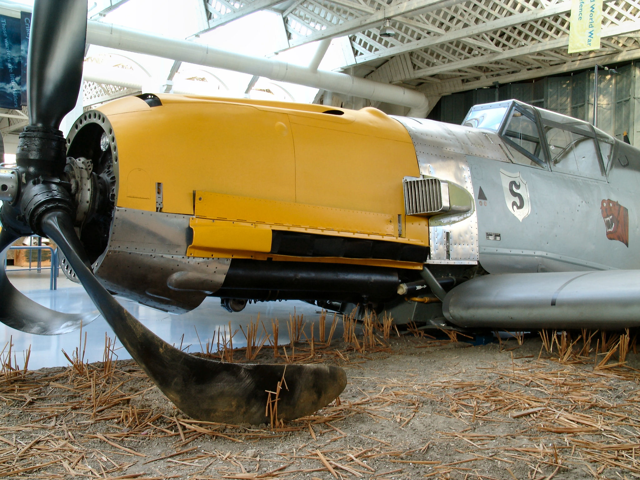 |
|
|
|
Post by wbill76 on Jan 18, 2014 21:08:42 GMT -5
Makes sense to me Marc! Here's another question for you...this kit has vinyl tires for the main gear and tail wheel. Do I need to do anything special with the hubs like sealing them with Future etc. to prevent issues with the tires or does that sort of thing only happen with the ancient style of vinyl that used to be put in kits?
|
|
|
|
Post by wbill76 on Jan 19, 2014 14:46:38 GMT -5
The work on getting the major components ready for painting continued with the assembly of the belly tank and mount as called for in Step 13. The tank itself is in two halves and getting it to mate up properly at the rear required some extra coaxing and pressure supplied with a smooth clamp to allow the glue to grab and hold properly. Once the tank had set, I sanded down the join seam and added the PE center band as well as the mounting hardware to the tank's top. The belly mount itself was attached to the wing underside instead of installing it to the tank to allow for a better join with the wing as well as make it easier to paint the tank itself. Part G5 from Step 14 was added at this point as well to provide the front half of the mount point for the tank mount.  Continuing with the underside elements, I went back to Steps 4 and 5 to deal with the main landing gear. The struts were assembled and ejector marks removed or filled where appropriate on the struts and covers. The PE straps for the brake lines were annealed and then attached using liquid glue to help position them properly on the struts. The two part wheel hubs were assembled and the vinyl tires cleaned up by gently sanding away their mold seam and trimming away flash on the insides of their rims with the point of sharp #11 blade.  Jumping back to Step 14, the underside engine cowl and intake were assembled with the kit-provided PE screen added. The cover will be painted separately prior to its installation.  Rounding out the session's activity, I added the rear extension plate to the cockpit that's installed separately in Step 10 as part of the fuselage joining process. I used the fuselage halves to dry-fit the part, L5, to line it up properly with the pilot's seat back and then carefully glued it in place while still inside the fuselage halves to give it some support so it would set at the correct level position. Once set, I added the PE mount for the top pilot's harness straps to get it ready for airbrushing.  It's been a bit of a surprise just how much time has been consumed by these steps to get stuff ready for painting but almost there! Just need to clean up the tail wheel mount and get the cockpit clear pieces masked and ready and some paint can start to fly on the various components. |
|
|
|
Post by wing_nut on Jan 19, 2014 18:53:08 GMT -5
Another question I cannot give a definitive answer. I don't have any experience with vinyl tire but I have read bad things liker them sweating and it eating at the plastic. I would hope by now they would have gotten past all that but sealing the rims can't hurt. If it were me I would have gotten resin replacements to avoid any problems. There in lies the rub... it's not me in this case  Since I am not used to you building aircraft I don't know how much of a stickler you are for accuracy. In the photo of the bottom of the wing the wheel wells are squared off. This was only on the very early F's up to early F2's. The plan was to have a small gear door there but it never came to pass so from the later F2's onward the wheel well was rounded off. |
|
|
|
Post by wbill76 on Jan 19, 2014 20:28:28 GMT -5
Appreciate it Marc! Definitely not being a stickler on this build so the wheel well inaccuracy isn't going to cause me to lose any sleep over it.  I'll seal the hubs as a precaution before using the kit-supplied wheels just to be on the safe side. |
|





 )and some cool streaking back from the seams.


