Post by mshackleton on Sept 5, 2012 4:16:03 GMT -5
PART 2
This carries on from Part 1 here:
modelerssocialclub.proboards.com/thread/3428/meng-tortoise-build-blog-1
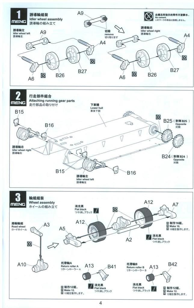
This is a view of the inside of the sideplates. The outer idler mounting plates have already been glued in position (B15 and 16) as noted before. Don’t follow the instructions by gluing them to the outer ends of the idler pivots as they will be left dangling at jaunty angles and impossible to locate accurately.

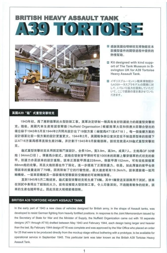
I read in another review that there were doubts about the accuracy of the dimensions as published sources vary quite a bit. Meng had direct access to the Tank Museum’s Tortoise (Prototype P1) so all I can say is that it must be right. Why rely on possibly inaccurate published material when your own tape measure tells the truth? Besides – the model looks right, so who cares?
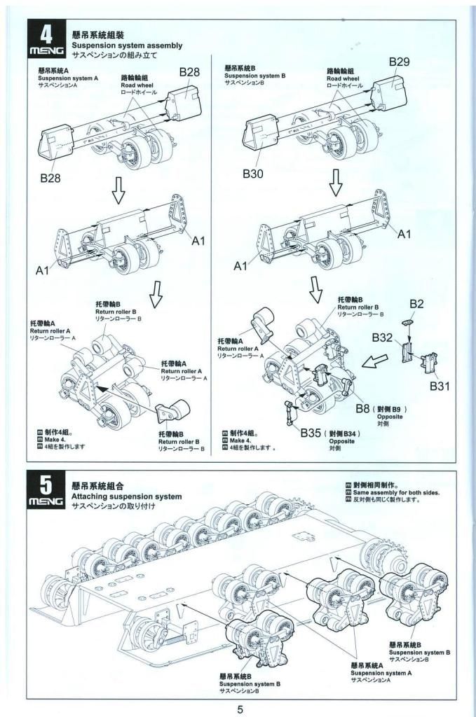
The instructions, quite logically, tell you to add all of the suspension components onto the hull sides and then add the side plates.
In the same review, the modeller had difficulty in lining up all of the components - sprocket, four suspension bogies, idler - with the raised locating ridges on the inside of the side plates. He had to remove all the ridges to make it work.
To circumvent this problem I tackled it my own way. I had already glued the idlers in place. I then took a sprocket and added a side plate. I glued the ends of the side plate (just the curved areas). This leaves the straight upper edge of the side plate unglued. The sprocket also stays unglued to allow it to rotate (necessary when fitting tracks). Leaving the sideplate largely unglued means there is a certain amount of give and each suspension bogie can be slid between the hull and the plate to locate on the ridges provided. Use normal tube cement as it’s difficult getting a brush load of liquid cement to the right places. It does work! Then run some liquid cement along the top edge of the side plate to complete the job.

Here is the running gear in place on one side and the other side awaiting its turn with the sideplate already in place.
You are now going to say that I’ve made a big mistake. What about the tracks I hear you cry? As I mentioned before, I don’t believe in building what cannot be seen. Some of you are not going to agree but this is my modeller’s choice. I prefer to paint tracks separately and add them later. I will build the tracks in three sections per side – the flat bottom run and the two curved sections at either end. With the sprocket left to rotate, it gives me some movement to fit the tracks accurately. There is no need to build the top run. More of this later.
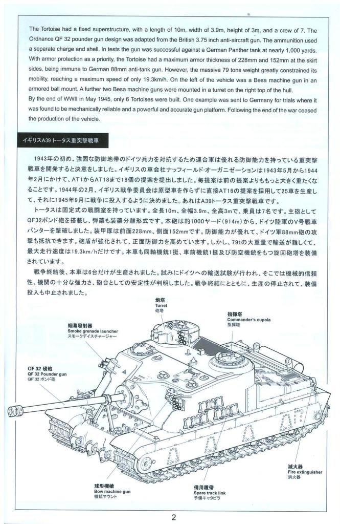
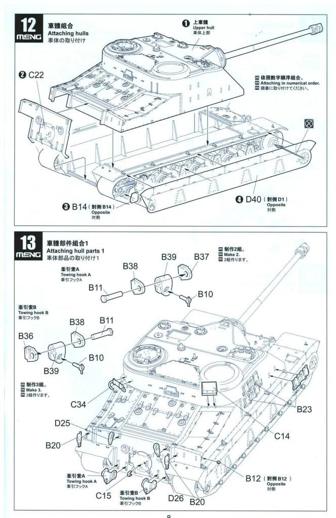
Here I have temporarily added the superstructure top to give you an idea of what the beast will look like.


Someone asked me about the size of Tortoise, so here is an M3A3 Stuart alongside to give you some idea.

Part 3 continues here:
modelerssocialclub.proboards.com/thread/3431/meng-tortoise-build-blog-3
And Part 4 here:
modelerssocialclub.proboards.com/thread/3453/meng-tortoise-build-blog-4
This carries on from Part 1 here:
modelerssocialclub.proboards.com/thread/3428/meng-tortoise-build-blog-1
This is a view of the inside of the sideplates. The outer idler mounting plates have already been glued in position (B15 and 16) as noted before. Don’t follow the instructions by gluing them to the outer ends of the idler pivots as they will be left dangling at jaunty angles and impossible to locate accurately.

I read in another review that there were doubts about the accuracy of the dimensions as published sources vary quite a bit. Meng had direct access to the Tank Museum’s Tortoise (Prototype P1) so all I can say is that it must be right. Why rely on possibly inaccurate published material when your own tape measure tells the truth? Besides – the model looks right, so who cares?
The instructions, quite logically, tell you to add all of the suspension components onto the hull sides and then add the side plates.
In the same review, the modeller had difficulty in lining up all of the components - sprocket, four suspension bogies, idler - with the raised locating ridges on the inside of the side plates. He had to remove all the ridges to make it work.
To circumvent this problem I tackled it my own way. I had already glued the idlers in place. I then took a sprocket and added a side plate. I glued the ends of the side plate (just the curved areas). This leaves the straight upper edge of the side plate unglued. The sprocket also stays unglued to allow it to rotate (necessary when fitting tracks). Leaving the sideplate largely unglued means there is a certain amount of give and each suspension bogie can be slid between the hull and the plate to locate on the ridges provided. Use normal tube cement as it’s difficult getting a brush load of liquid cement to the right places. It does work! Then run some liquid cement along the top edge of the side plate to complete the job.

Here is the running gear in place on one side and the other side awaiting its turn with the sideplate already in place.
You are now going to say that I’ve made a big mistake. What about the tracks I hear you cry? As I mentioned before, I don’t believe in building what cannot be seen. Some of you are not going to agree but this is my modeller’s choice. I prefer to paint tracks separately and add them later. I will build the tracks in three sections per side – the flat bottom run and the two curved sections at either end. With the sprocket left to rotate, it gives me some movement to fit the tracks accurately. There is no need to build the top run. More of this later.
Here I have temporarily added the superstructure top to give you an idea of what the beast will look like.


Someone asked me about the size of Tortoise, so here is an M3A3 Stuart alongside to give you some idea.

Part 3 continues here:
modelerssocialclub.proboards.com/thread/3431/meng-tortoise-build-blog-3
And Part 4 here:
modelerssocialclub.proboards.com/thread/3453/meng-tortoise-build-blog-4


 ;D
;D


