|
|
Post by mustang1989 on Mar 1, 2023 6:05:58 GMT -5
Man.....you guys know stuff about armor subjects that I don't even know about cars for cryin' out loud. This is some intense study but it's the kind of stuff that I enjoy doing as well. I really do love digging into the research involved in making an accurate model.
That PE with the jack looks awesome Brian. It's all in the details bro.
|
|
|
|
Post by hasenpfeffer on Mar 1, 2023 7:18:32 GMT -5
Hey Brian, So, I'll sorta give my 2 cents... I suppose take caution, cuz sometimes I don't really know what I'm talking about and just go on perception. As far as the welds go, Tobi is right on the plate thickness, but I'm not so sure on the weld orientation. When welding they follow the plate join seam and the material build-up that we perceive as those cool looking wavy lines follows the tool path. (Or workers path). So I don't see how you could get lines parallel with the plate (seam) lines unless they do separate individual welds side by side which would be a waste of time. Even Tobi's picture of the Panther G shows at least a severe angle (compared to parallel) on the horizontal welds. All this is to say that I think the weld lines are pretty much perpendicular to the weld path taken - which follows the plate seam line. So I think you got it right. As for the texturing... I often think it is over done. For cast parts, go ham. For rolled steel I think it turns out too severe for reality. But again, my opinion. The late war tank's rolled steel is definitely rougher than early and mid war tanks. I've seen Panzer IIIs in museums that have a rough texture, but I have had a hell of a time finding pictures taken at the time showing that same roughness. I posit that it could be pitting from sitting in the elements for so many years. But??? This is where a time machine would come in handy and a few hours with each subject and a modern camera. LOL. I find Tobi's pic very interesting in the fact you can see a cast seam on the mantlet. Cool. The ball mount machine gun housing is very interesting also, if it is original. Cast with many machine planes. Anyway - this isn't meant to be a rant, or even rivet counting, just my opinion... I think you are doing a great job on this bad boy. The PE is a pain sometimes, but it is rewarding when it works out. Looks great too. Practice makes better ya know. It's all a function of how crazy deep down the rabbit hole you wanna go and how fun/rewarding that is for you. Cheers Dave, you've brought up some very good points and for the welding I admit that my first statement about weld beads is somewhat mistakable as if it's a general rule, but only something I have observed on (severall) occasions. To be exactly sure you would need to study every single weld bead from the original. But to illustrate my point here is a glacis plate of a Tiger B in La Gleize. One can see how the orientation of the welds on the extended hull side was changed out of nowhere, most likely as you say because of the working position of the welder. If I look closely at the ball mount, I have again the impression all welding is horizontally. It's been almost 30 years since I've been welding for the last time and it was no armored steel, but I imagine it is difficult to follow the shape of the circle going round, because you will get more material on the inner edge of the ball mount, than on the outer edge of the glacis plate?  Brian, your statement is making me a tiny bit embarrassed.  I would have to look up the jack installation like most of us, before I'd even dare to comment. What appeared a little strange to me at first is the handle so close to the exhaust pipe, but I found it is documented in photographs. I would have expected a foldable handle, so you can never know. Cheers to you too Tobi! I absolutely appreciate the discussion. I was wrong and learned something today. They did use them. The parallel welds are very interesting to me. It makes me wonder more now where they were used and why. It looks to me like those are a build up of several (smaller) welds. Maybe due to the plate thicknesses involved (?) more than the operator orientation. Maybe this was the only way to join two such plates at the time. (For whatever reason.) My gut feeling is that these can't be as strong as a regular, single continuous weld, but again I am no weld expert and have no welding experience. LOL What my eyes are seeing and what is the reality could be way off too. It still looks to me that the weld bead is circular around the ball mount. It's really hard to tell on the lower left due to the pic orientation and general roughness of the surface, but it looks that way to me on the lower right (looking at the mount, not from behind the mount). Again, I am not being a rivet counter by any means, even though I do it on occasion for my own builds. I am all for builder interpretation and in many cases just what looks more pleasing. With the amount of field repairs, upgrades and just crews messing around with their vehicle you can probably pretty much do anything and find an example somewhere.  And Brian, I totally did not mean that you shouldn't roughen the surface, or that you even did it wrong in any way. I guess I was just thinking to myself that it seems to be a trend these days to put a rough texture on everything that is an armor plate and I don't think it is always the case. So I apologize if it came across that way. I did find a pic that shows what Tobi correctly pointed out. It's so hard to find any that are close enough to show any detail and aren't obscured in some way or covered with zimmerit. 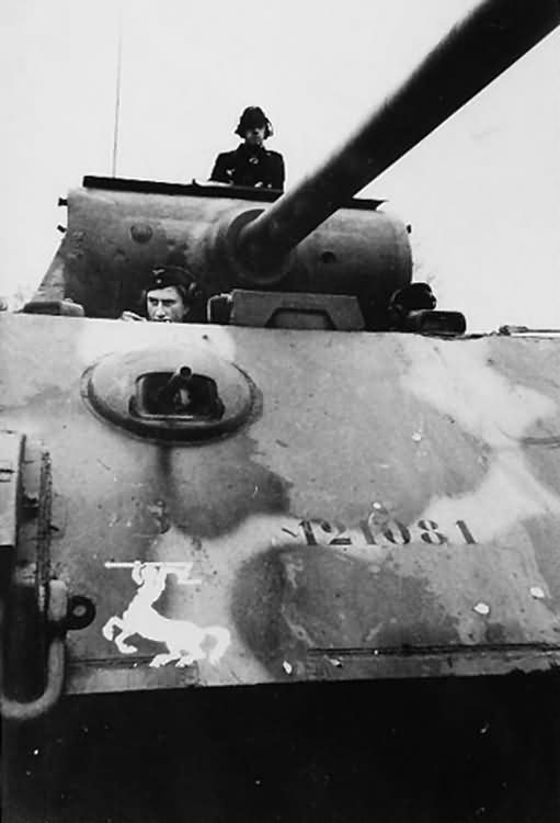 |
|
|
|
Post by chromdome35 on Mar 1, 2023 9:27:13 GMT -5
No need to apologize at all, your comment about texture was spot on. I had already been feeling the effect I applied was too much and needed toning down, so I went ahead and did it and am much happier with the result.
|
|
|
|
Post by Tobi on Mar 1, 2023 12:00:01 GMT -5
Brian is right, no need to apologize at all, Dave. It's such fun and pleasure to have forum members again for good discussions, giving tips and sharing thoughts! That said, I couldn't agree more with you about the parallel welds. My thinking goes in a similar direction. I learned this type of weld build-up in my early days as student, and I think I remember it is actually for large parts where heat input is difficult. If you look closely you can still make out that the welder did a wave movement with his wrist also on these. Regarding the durability one would also have to take into account the forces in the completed part. On this edge I would expect most of all torsion from the hull, so the glacis plate and the side plate would want to slide along each other. If that's the case the weld beads would be orientated perfectly this way from my point of view, because a weld bead can take shear or push better than bending. Or it is really just a matter of "soldering" the darn thing water tight and let the interlocking of the plates do the job of keeping everything together.  I honestly don't know and I'm available to stand corrected if someone can give an explanation.  |
|
|
|
Post by chromdome35 on Mar 1, 2023 12:07:16 GMT -5
One thing you can see pretty clearly in this picture is the hull texture. It also appears there are some remnants from an old paint job.  |
|
|
|
Post by hasenpfeffer on Mar 1, 2023 21:53:47 GMT -5
One thing you can see pretty clearly in this picture is the hull texture. It also appears there are some remnants from an old paint job.  For sure. My point from earlier is that it's hard to tell the current state vs. 1944/45. This thing has been sitting in that spot since the Battle of the Bulge. IIRC it's also been painted multiple times. I seem to remember pictures taken with worn paint and like Tobi presents here. Depends on when one visits it I guess. You can even see some of the green paint "runs". But yes, the surface did have texture because of the reasons Tobi gave previously. Like I was alluding to earlier, without time travel and some serious geek time, this is the best we have to help interpret the reality of the period. There's a pretty good history of this tank if you go looking. Both pics and vids. I know if I was in Europe for any length of time I'd visit this beauty.  |
|
|
|
Post by chromdome35 on Mar 10, 2023 1:48:05 GMT -5
The downside to buying PE is you have to assemble it. Even in the slightly larger scale of 1/25, much of it is tiny. So I'm inching along. Switched out the molded in latches on the rear stowage boxes.   Then I focused on the rear deck grills. This required me to solder a band all the way around this circular frame. You can make out the band in the picture below. I accomplished this by soldering it at one spot to start, then slowly progressing my way around the frame, one spot at a time. It came out ok. I felt pretty good when I got it done. I don't think I could have done it without this honeycomb soldering board.  Here it is on the part along with some other photo-etch work on the vanes.  After the circular grills were done, I did the rectangular grills. The two grills on the right have a sliding panel between the grill and the top plate.  Slowly but surely progress is being made. |
|
|
|
Post by mustang1989 on Mar 10, 2023 7:09:52 GMT -5
That added a whole new look to what was once molded in details. PE is hard to work with in dang near any scale. The larger scales tend to have even more detail resulting in a thousand tiny a$$ pieces that need to be dealt with. Seems like the larger the scale the more crazy/ difficult things become. Great result on your efforts Brian. An example of larger scale PE. Folks..........I dang near hung it all up as far as modeling goes putting this 1/25 scale shifter together for my Ford Maverick. This offering is from Future Attraction and it aint no joke at 26 pieces....... 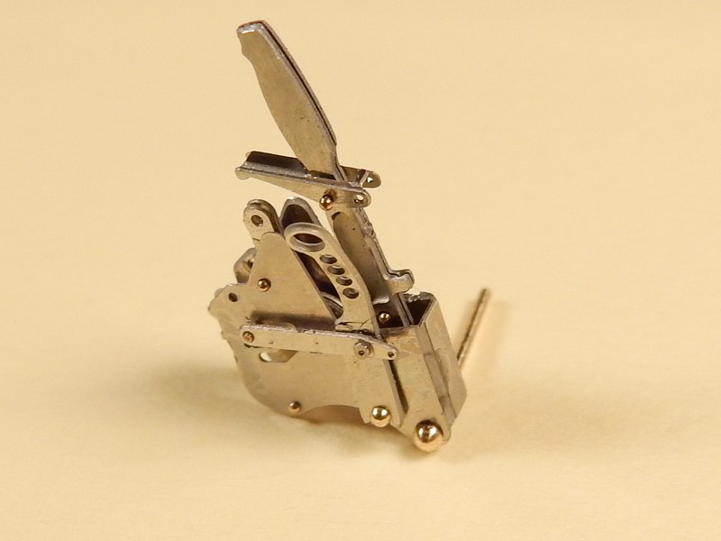 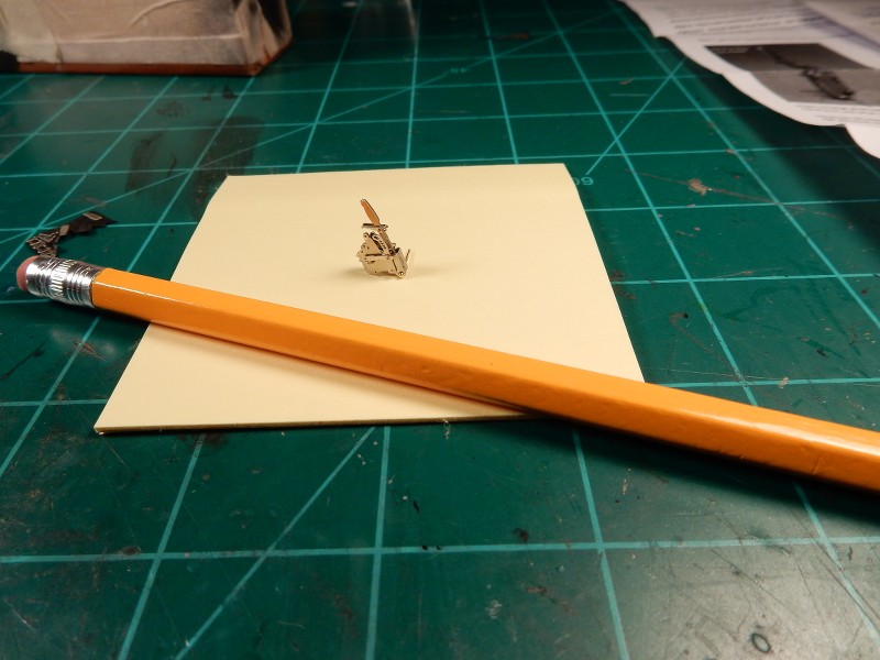 |
|
buddho
Forum Moderator     
Member since: February 2019
Posts: 1,287 
MSC Staff
|
Post by buddho on Mar 10, 2023 7:33:10 GMT -5
Vast improvement on the PE details. Makes all the difference. That shifter is incredible, too.
|
|
|
|
Post by Tobi on Mar 10, 2023 10:17:04 GMT -5
That added a whole new look to what was once molded in details. PE is hard to work with in dang near any scale. The larger scales tend to have even more detail resulting in a thousand tiny a$$ pieces that need to be dealt with. Seems like the larger the scale the more crazy/ difficult things become. Great result on your efforts Brian. An example of larger scale PE. Folks..........I dang near hung it all up as far as modeling goes putting this 1/25 scale shifter together for my Ford Maverick. This offering is from Future Attraction and it aint no joke at 26 pieces.......   But the shifter was the best part!!! Nice progress Brian. |
|
|
|
Post by hasenpfeffer on Mar 10, 2023 22:09:17 GMT -5
As much of a pain that it is... it looks awesome if you can get through putting it together. Nice work there. tough enough soldering flat/straight surfaces together. You did a great job on that circular edge.
and Joe, stop with the masochism.
|
|
Whiterook
Full Member
  
Member since: March 2013
Modeler & Wargamer
Posts: 905
Mar 13, 2013 15:29:19 GMT -5
Mar 13, 2013 15:29:19 GMT -5
|
Post by Whiterook on Mar 27, 2023 16:45:26 GMT -5
Just went through this one and man, what an amazing build you’ve got going on here!!! All that PE alone would task my skills and patience! Great work. Soldering? …OMG, I can’t even imagine! And that’s a hell of a scale! On the question of instruction highlighting and notation, yes, I do that, as well. I cross off the pieces I’ve completed as I go, too…so I don’t get lost in the sauce! The instructions on some built kits could be used as artwork, haha. I note you using Mr. Cement S… what is the difference between S and SP? I saw SP being used elsewhere and it now has me wondering. Love your workspace! I generally keep my area clean, but my wife has a habit of dumping wandering items of mine on it… I think that’s planned, actually!  Just a wonderful build, my friend! I have a soft spot for these beasties so, following along closely! |
|
|
|
Post by chromdome35 on Mar 27, 2023 17:08:05 GMT -5
Just went through this one and man, what an amazing build you’ve got going on here!!! All that PE alone would task my skills and patience! Great work. Soldering? …OMG, I can’t even imagine! And that’s a hell of a scale! On the question of instruction highlighting and notation, yes, I do that, as well. I cross off the pieces I’ve completed as I go, too…so I don’t get lost in the sauce! The instructions on some built kits could be used as artwork, haha. I note you using Mr. Cement S… what is the difference between S and SP? I saw SP being used elsewhere and it now has me wondering. Love your workspace! I generally keep my area clean, but my wife has a habit of dumping wandering items of mine on it… I think that’s planned, actually!  Just a wonderful build, my friend! I have a soft spot for these beasties so, following along closely! I only used the Mr. Cement S to do some of the armor texturing, for joining pieces together I use TET. I don't really know the difference in the Mr. Cement S and SP. I am slowly making progress, been on the vacation and slammed with work which both have conspired to keep me busy. Thank you for the kind words! |
|
|
|
Post by chromdome35 on Apr 4, 2023 22:32:17 GMT -5
I need the board's collective wisdom. I have been stalled on this build because I realized I missed installing the hull periscopes before I joined the body halves together. I've done too much work beyond this point to back up. I don't want to move forward with adding more detail until I solve this. I've been trying to solve this problem for 2 weeks. This is the periscope, there are two of these These mount from below the hull per the instructions These mount from below the hull per the instructions The problem is that with the hull halves joined, I can't reach the openings with anything that allows me to apply pressure to hold them while I glue them in place. I've tried every style of tweezer or curved hemostat I have. The problem is that with the hull halves joined, I can't reach the openings with anything that allows me to apply pressure to hold them while I glue them in place. I've tried every style of tweezer or curved hemostat I have.
I consider these a "must include" otherwise there will just be big open holes where they are supposed to be. I'm down to two options unless any of you have ideas: - Attach a flat piece of styrene below the opening, saw the visible portion of the periscope off, and attach it to the flat piece of styrene.
- Make some kind of jig to hold the periscope vertically and lever it upwards with enough force to hold it in place while I glue it.
I would very much appreciate any thoughts on this you might have. |
|
|
|
Post by Tobi on Apr 5, 2023 1:00:30 GMT -5
Since it will not require a lot of pressure I would try to insert temporarily a large piece of foam to hold them in place.
Or you flip the hull upside down until the glue has settled.
Or didn't I get the problem?
|
|
|
|
Post by tcoat on Apr 5, 2023 6:38:57 GMT -5
Not sure I understand the issue. Looks like ("looks" being the key word here) there is loads of room to get the parts into place with some cured tweezers. A drop of extra thin cement from above should dry enough to hold the parts in place in about 5 seconds. Shouldn't have to hold firmly for any period. Or am I missing something?
|
|
|
|
Post by chromdome35 on Apr 5, 2023 8:09:36 GMT -5
Not sure I understand the issue. Looks like ("looks" being the key word here) there is loads of room to get the parts into place with some cured tweezers. A drop of extra thin cement from above should dry enough to hold the parts in place in about 5 seconds. Shouldn't have to hold firmly for any period. Or am I missing something? This is exactly what I've been trying to do, use curved tweezers. The problem is I can't get the periscope to insert far enough into the opening. When I first began, I thought "This shouldn't be too hard", turns out it is much more difficult than it looks like it ought to be. Tobi's idea of doing it upside down might work. |
|
|
|
Post by chromdome35 on Apr 5, 2023 8:12:20 GMT -5
Since it will not require a lot of pressure I would try to insert temporarily a large piece of foam to hold them in place. Or you flip the hull upside down until the glue has settled. Or didn't I get the problem? Thank you! I had not considered trying it upside down. Sometimes you lose sight of the forest for the trees. I'll try this today. |
|
|
|
Post by Steve Zuleski on Apr 5, 2023 9:53:21 GMT -5
Yep, you got this.
So, sounds like you might have needed a third hand, lol. Ah, how many times could we use a third hand, and a qualified third hand, right? Ruck On, Brian, standing by for more.
|
|
|
|
Post by chromdome35 on Apr 5, 2023 10:07:57 GMT -5
Yep, you got this. So, sounds like you might have needed a third hand, lol. Ah, how many times could we use a third hand, and a qualified third hand, right? Ruck On, Brian, standing by for more. I'd settle for two non-hamhanded, shake-free hands. |
|
|
|
Post by tcoat on Apr 5, 2023 12:29:36 GMT -5
Since it will not require a lot of pressure I would try to insert temporarily a large piece of foam to hold them in place. Or you flip the hull upside down until the glue has settled. Or didn't I get the problem? Thank you! I had not considered trying it upside down. Sometimes you lose sight of the forest for the trees. I'll try this today.  |
|
|
|
Post by chromdome35 on Apr 5, 2023 12:32:03 GMT -5
Thank you! I had not considered trying it upside down. Sometimes you lose sight of the forest for the trees. I'll try this today.  Ok, that made me laugh!!!     |
|
|
|
Post by hasenpfeffer on Apr 5, 2023 14:18:10 GMT -5
Hey Brian, I think I'd try to build some sort of "L" shaped jig that fits easily thru the hatch that you could attach the periscope to with maybe something tacky like tape or poster putty? You could work it into position and then use extra thin from the top like previously mentioned. When it's dry enough you can remove the jig. Probably won't matter if the tape or putty doesn't come along for the ride home.
|
|
reserve
Senior Member
   
Member since: July 2012
Si vis pacem para bellum
Posts: 2,372
Jul 11, 2012 9:11:45 GMT -5
Jul 11, 2012 9:11:45 GMT -5
|
Post by reserve on Apr 5, 2023 16:59:18 GMT -5
Cut some holes in the bottom of the hull big enough so you can use your tweezers from directly below to locate and glue the periscopes. Once done, fill the holes and presto. Not gonna be an interior kit anyway, and who's gonna know?
|
|
|
|
Post by tcoat on Apr 5, 2023 18:19:17 GMT -5
I see only one issue of concern here, Brian,...................your desk is way too clean! Ruck On! My work area is pretty small and it drives me crazy to have stuff laying all over the place. So normally I "clear the decks" every day and put up everything I'm not currently using. I set my space up to be modular. I have setups for: Building Painting Weathering Soldering LOLOLOLOLOLOLOLOLOLOLOL This is my set up for: Building Painting Weathering Soldering Post to forums Photoshop Up coming project storage TV watching Socializing Cat petting Video game playing Eating Drinking Napping Butt scratching 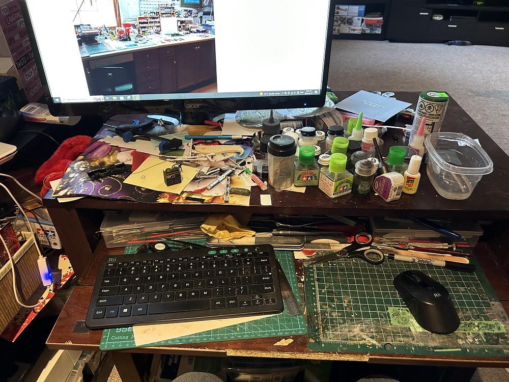 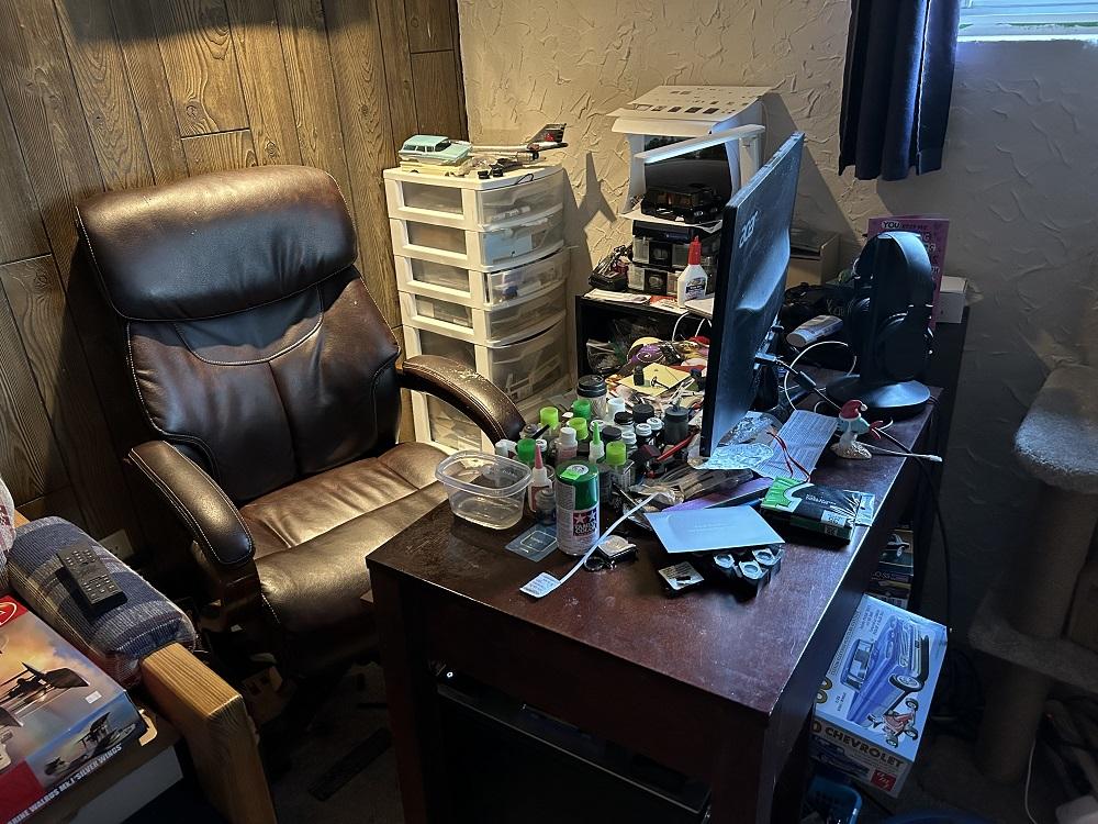 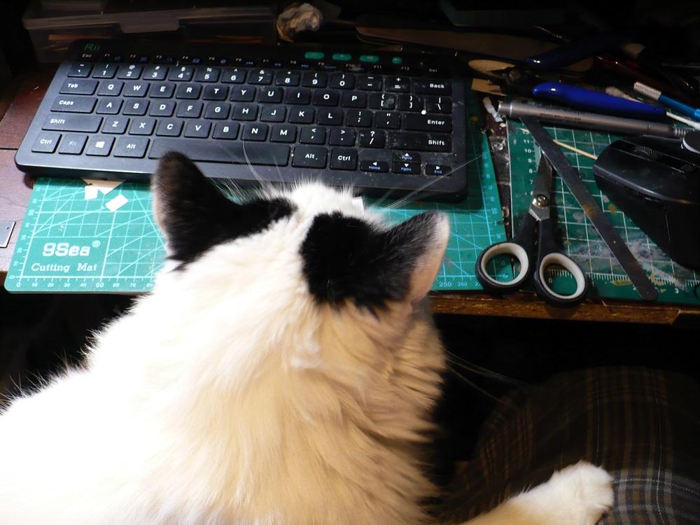 |
|
Whiterook
Full Member
  
Member since: March 2013
Modeler & Wargamer
Posts: 905
Mar 13, 2013 15:29:19 GMT -5
Mar 13, 2013 15:29:19 GMT -5
|
Post by Whiterook on Apr 6, 2023 16:59:10 GMT -5
OMG
|
|
|
|
Post by mustang1989 on Apr 6, 2023 19:23:35 GMT -5
As much of a pain that it is... it looks awesome if you can get through putting it together. Nice work there. tough enough soldering flat/straight surfaces together. You did a great job on that circular edge. and Joe, stop with the masochism. Didn't see this when you posted it. LOL! |
|
m1keh
Full Member
  
Member since: April 2023
Posts: 259
Apr 9, 2023 23:03:02 GMT -5
Apr 9, 2023 23:03:02 GMT -5
|
Post by m1keh on Apr 9, 2023 23:07:42 GMT -5
If you are still working on how to get the periscopes in how about you put some putty on your fingertip, stand the periscope upright in the putty and just reach up through the turret ring?
|
|
|
|
Post by chromdome35 on Apr 11, 2023 21:53:08 GMT -5
Success, sort of... So I ended up building a jig and putting blue tac on the end of it to hold the periscope. This ended up getting the job done; however, the driver periscope would not go all the way up into the opening no matter how I tried. So it is slightly lower than it should be. This will be covered by the sunshade so it shouldn't be a major issue.    I want to thank everyone for offering their advice on solving the issue, it was one of those "its harder than it looks moments". I started working on the driver's side tools and externally mounted stuff. Let me tell you about filling ejector pin markings. In this older Academy kit there are LOTS of them to be filled and sanded.  One of the extra details I'm adding to this kit is adding the stowed track retention pins and chains. To do this, I had to drill out small holes in the track holding bracket. I didn't get them all perfectly centered, but I don't think this will be very noticeable on the finished model.  Into these holes will go small L pins. I'm still working out the correct dimensions, the top part of the pin is too long.  Inching along... |
|
ogrejohn
Full Member
   Oct '23 Showcased Model Awarded
Member since: June 2012
Go away or I shall taunt you a second time!
Posts: 1,302
Jun 1, 2012 17:33:59 GMT -5
Jun 1, 2012 17:33:59 GMT -5
|
Post by ogrejohn on Apr 12, 2023 16:34:06 GMT -5
Wow, that is a whole lot of EP marks to fill. Looks like you're getting it whipped though. Nice work on getting the periscope in.
|
|