|
|
Post by Leon on May 28, 2015 20:18:52 GMT -5
Great progress Bill! Shaping up nicely.  |
|
|
|
Post by deafpanzer on May 28, 2015 21:38:53 GMT -5
Looking great!!! Tell your mom I said hi!
|
|
reserve
Senior Member
   
Member since: July 2012
Si vis pacem para bellum
Posts: 2,372
Jul 11, 2012 9:11:45 GMT -5
Jul 11, 2012 9:11:45 GMT -5
|
Post by reserve on May 29, 2015 9:11:50 GMT -5
I was wondering what kind of a dance it was going to be to get the superstructure fit on this beastie. Not as complex as I'd imagined but a lot of stuff to juggle at once...does it not say somewhere on the box "Engineered for ease of assembly and maximum modeling enjoyment"?
Nice job brother
Regards,
Mark
|
|
|
|
Post by wbill76 on May 29, 2015 11:34:27 GMT -5
Thanks Leon! Slugging away on it and gaining ground!  Andy Andy, will do, just remember Mom = Katherine, Wife = Sharon!  I was wondering what kind of a dance it was going to be to get the superstructure fit on this beastie. Not as complex as I'd imagined but a lot of stuff to juggle at once...does it not say somewhere on the box "Engineered for ease of assembly and maximum modeling enjoyment"? Nice job brother Regards, Mark Thanks Mark! On the bottom under the Smart Kit label it says "Engineered for modeling enjoyment, Plastic parts with enhanced detail, Unprecedented value, and Ready for instant Assembly!".  Got to love those marketing geniuses, eh?  In fairness to the engineering, it does fit all together as it should, you just can't get it to that point if you follow the instructions!  I've always said that those two departments don't talk to each other at Dragon as it's obvious that they don't a) proof their instructions or b) actually try to build the kit with the instructions AFTER the molds have been done and the test shots run.  Either that or they just don't care and get a perverse joy out of seeing modelers try to figure it out for themselves. That's what makes it model building and not assembling I guess, right?  |
|
|
|
Post by Tojo72 on May 29, 2015 12:23:17 GMT -5
Moving along nicely Bill
|
|
|
|
Post by wbill76 on May 29, 2015 17:21:17 GMT -5
Thanks Anthony! Moving much faster than the previous project for sure! No turret, no interior, etc. definitely speeds things along.  |
|
|
|
Post by wbill76 on May 30, 2015 15:48:19 GMT -5
Latest round of effort moved to the casemate and gun as called for in Steps 11-14. The breech and recoil guards are dealt with in Step 11 and Step 12 adds the mount details, gun barrel, gunner's sight, and the elevation and traverse wheels. It all goes together without any issues and the gun remains able to elevate via friction connection with a toothed gear that slips inside the left side of the gun mount support. Just make sure you insert the gun barrel and breech through the recoil guards and ball mount before adding the back pad, G6, to the recoil guards. 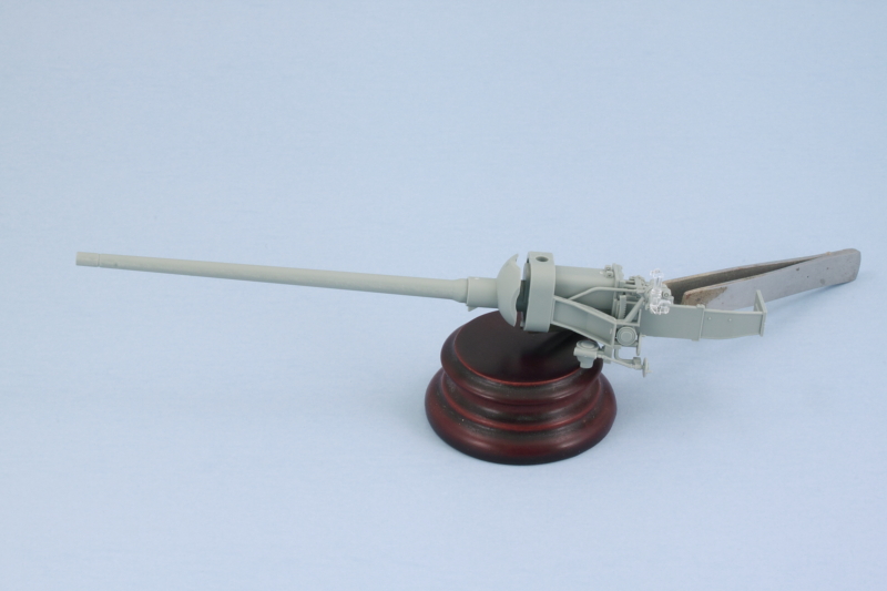 Step 13 is a pretty simple step, it adds the interior plate to the front of the casemate along with the exhaust fan and the mount for the hull MG port. No gun is provided though, just the simple ball mount and tray for one is present. The little ball tray is numbered wrong in the instructions, it's actually C23 and not C22. Last but not least for this step is the addition of the clear periscopes for the driver. 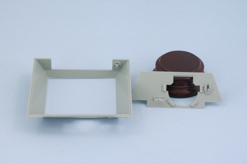 Step 14 is the moment of truth when the whole gun is installed along with the cast external mantlet components. This almost requires three hands to get it all together and still allow the gun to traverse slightly. You also have to avoid gluing the base of the mount, G29, to the gun itself and only glue it to the top part of the mount, G31. This sandwiches the gun in between the two halves and the real C22 large pin connects at the top completing the full assembly. This gets glued to the front plate of the casemate and supports the whole deal rather nicely once you get it all in place. The saukopf mantlet then slides over the barrel to complete things for the gun. I also added the armored conical port for the hull MG in the closed position and the welded armored cover for the driver's periscopes. Ironically this last detail makes it all but impossible to tell that there are clear periscopes behind it but we all know they are there from the previous step. 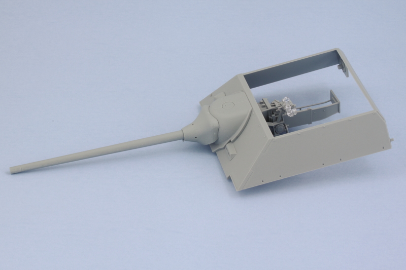 A quick test with the hull shows everything is lining up properly and the gun can be both elevated and traversed properly. This is useful not just for painting later on but also if you wanted to pose the gun with the travel lock engaged or traversed off to the side slightly for diorama purposes. 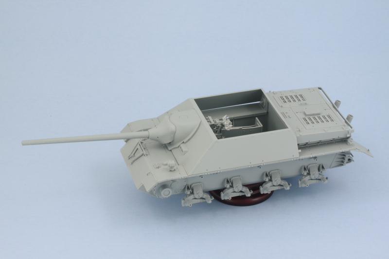 Next up will be tackling the casemate roof details and components. |
|
|
|
Post by Leon on May 30, 2015 18:16:03 GMT -5
Great update Bill! Nice work on the gun and assembly.  |
|
|
|
Post by JimD on May 30, 2015 18:25:46 GMT -5
Late to the party as usual it seems. I am particularly fond of all thing "Jagd" so I'll catch up and join in the fun. I ran across masking for that disc camo online the other day and am intrigued to see you pull that off. Looks good so far. More please.
|
|
|
|
Post by TRM on May 31, 2015 8:10:45 GMT -5
Nicely done so far Bill!! Shaping up well! I have my finger on the trigger for another one of these myself...now!!  I have to be strong...LOL! Keep up the great work! |
|
elco
Full Member
   July & Oct 2014 MoM Winner
Member since: May 2013
MOY 2014 Winner
Posts: 660 
|
Post by elco on May 31, 2015 11:48:05 GMT -5
Looking good so far, are you planning extra texture to the armor plates? I found it a big plus on my build.
|
|
|
|
Post by wbill76 on May 31, 2015 12:50:29 GMT -5
Thanks Leon! Jimmy, just chalk it up to the extended vacation!  The disc masks should be an interesting exercise as it will be the first time working with them. We'll see how it goes.  Todd Todd, you have to stay strong brother!  Elco Elco, thanks as always! No plans for added texture on the plates for this one. Was tempted to do it but decided not to so as to have as 'clean' a surface as possible for playing around with the masks when the time comes for the disc camo. |
|
|
|
Post by tonylee-Rest In Peace on Jun 1, 2015 12:47:53 GMT -5
You're gaining on it Tex  Dots are no big deal for a high stepper like you William  Tony lee |
|
|
|
Post by wbill76 on Jun 1, 2015 12:59:15 GMT -5
Thanks Tony! Appreciate the vote of confidence as well.  Will try to make a decent job of it.  |
|
|
|
Post by wbill76 on Jun 1, 2015 15:47:48 GMT -5
Got the last of the major construction steps done in the latest round of progress. Steps 15-17 in the instructions cover the casemate roof and all the various hatch-related details. Since there's no interior to speak of, I decided to close up all the hatches except for the small 'rabbit ears' scope hatch for the commander. The kit provides the option for that small hatch to have a separate hinge point which makes life a lot easier in many ways, so the hinge point was added and the hatch put off to the side for painting and later installation to avoid complications with the camo scheme application. Since I had no need for the gun to be traversed, I opted for the one-piece sliding cover for the gunner's sight. The advantage of the gun being able to traverse is still helpful as it made sure I had the sight and the opening on the part all properly lined up. I also opted for the close-in-defense weapon to be installed on this vehicle and added the appropriate cover. Getting the cover to line up is a little tricky due to the fact that it doesn't have the locater pins like the standard blanked-off cover does, a side-effect of the 'extra' sprue that Dragon throws into the kit for this little feature. Last but not least, all the clear periscopes were installed and some enamel Silver applied to their back faces and the front faces masked with small amounts of blue tack before the covers were added. The roof plate was then glued down and allowed to sit. Once it was set and no longer subject to flexing, the casemate was permanently joined to the lower hull courtesy of finger pressure and some strategic rubber bands. 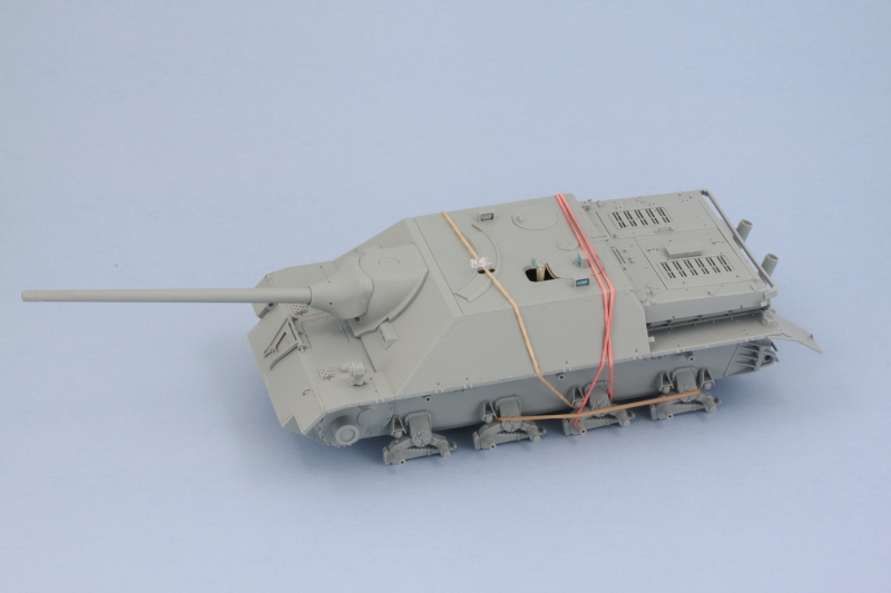 After that had set overnight, the last remaining details from Steps 18 and 19 were added in the form of the side skirt hangers and the antenna base. For the antenna, I clipped off the rod portion and drilled out the base with a #76 finger drill so it can take a brass 2m antenna later on. Since I had added the engine deck already to the hull, the rearmost pair of hangers needed the small tabs at the top that match up with the slots on the engine air intakes clipped off so that they could fit into the locater holes in the fenders correctly. The little fastback wing plates were also added and also needed a small modification to fit correctly. The molded on bracket designed to meet up with the rear rectangular support isn't the right size to match up correctly so all but the top part of the molded support outline on the plate was trimmed back so it would sit properly with the other two points. 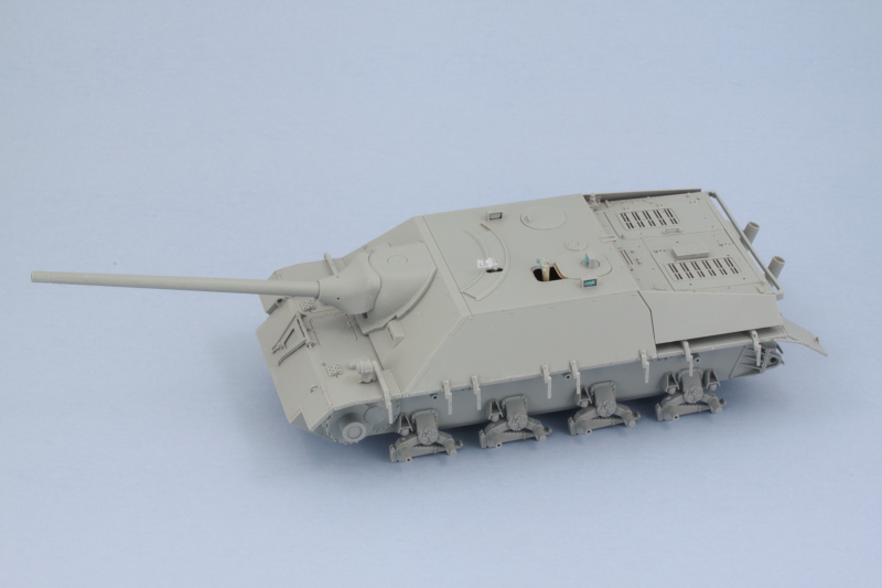 I'm still waiting for my disc camo stencils to come in the mail that I ordered from the Uschi site, so in the meantime I'll be working on the tracks and the tools and such before starting the major paintwork. |
|
reserve
Senior Member
   
Member since: July 2012
Si vis pacem para bellum
Posts: 2,372
Jul 11, 2012 9:11:45 GMT -5
Jul 11, 2012 9:11:45 GMT -5
|
Post by reserve on Jun 2, 2015 8:49:48 GMT -5
Nice! Swifty build compared to the last one eh?
Regards,
Mark
|
|
|
|
Post by wbill76 on Jun 2, 2015 11:20:12 GMT -5
Nice! Swifty build compared to the last one eh? Regards, Mark Like opposite ends of a spectrum Mark!  |
|
|
|
Post by Deano on Jun 2, 2015 13:54:26 GMT -5
You are in 1st gear with this build mate , gotta luv the ole smart kits . Its probably the biggest thing I miss about 1/35 , keep it coming Bill  |
|
|
|
Post by wing_nut on Jun 2, 2015 14:26:29 GMT -5
Really makes me want to build a tank. This one for example  |
|
|
|
Post by JimD on Jun 2, 2015 14:42:23 GMT -5
Well that came together pretty quickly. Looks great, but paint makes everything better, so hopefully you get those masks soon.
|
|
|
|
Post by wbill76 on Jun 2, 2015 17:33:39 GMT -5
Deano, I hear you buddy! The Dragon Pz IV Smart Kit family of kits rank up there in ease of build IMHO...that and the spare parts count in each box!  Marc Marc, now why doesn't that surprise me?  My telepathic influence seems to come and go in terms of deciding what you will or won't build next.   Jimmy Jimmy, construction is only the first step of course, but it does go quicker with the Jagd-type of subjects. Paint, tracks, tools, etc. still to be done so plenty to keep busy. I had to order the stencils from Germany so hopefully they don't take too long to arrive. I've ordered stuff from Poland and the UK on a regular basis and it can be kind of hit or miss in terms of total transit time but usually a couple of weeks is about right. I ordered these back on the 12th of May so it's starting to be about time for them to arrive I hope. 
|
|
|
|
Post by Leon on Jun 2, 2015 17:43:52 GMT -5
Just got caught up on yesterdays post and the JP is looking great Bill!  |
|
|
|
Post by wbill76 on Jun 2, 2015 18:52:35 GMT -5
Thanks Leon! Doing my best on this one a little at a time.  |
|
|
|
Post by wbill76 on Jun 4, 2015 17:37:17 GMT -5
Since the rear engine deck is really the only available place for stuff, it's a busy place as all the tools and such that would be on the fenders got placed wherever there was an empty spot! I spent some time getting all the tools cleaned up and prepped for painting. Due to all the tight spaces, I decided not to fully replace the tool clamps but instead removed the relatively thick handles and replaced them with PE handles from a generic Griffon tool clamps PE set. I also took advantage of the Magic Tracks in the kit to provide the 17-link spare track run. The instructions don't provide any guidance here and since the MK track set only has 8 spare links available, I cleaned up 20 links and did a test first to see how many would fit before settling on the 17 link arrangement. For no particular reason, I chose the links from the light grey bag and drilled out the pin holes on the one end and added the missing exposed pin on the other using short lengths of 0.5mm white styrene rod. Some quick work with a sanding stick removed the raised ejector marks on either side of the guide horns. Small amounts of Testors regular glue was used to assemble the run to ensure adequate work time to place and shape it properly in the mount without risking it becoming stuck to the rear hull or holder in the process. The jack is the only tool that has the potential for interacting with the spare track run, so it has to be factored into the equation as well. The spare wheel holder parts were left off for now to make life easier in terms of painting the engine deck and including it in the camo pattern. Everything is dry fit at this point and playing nice with each other, always a plus! 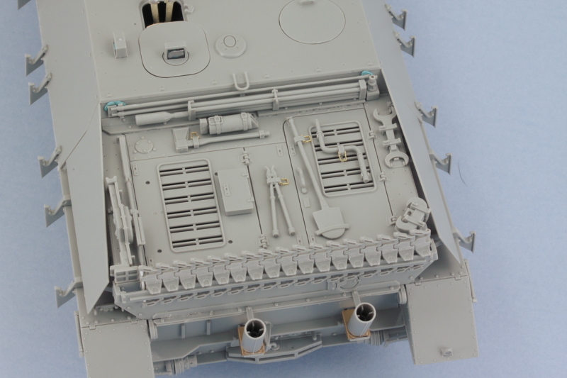 |
|
|
|
Post by dierk on Jun 5, 2015 7:27:45 GMT -5
Coming together nicely Bill! I approve very much of the 'lazy man's approach' to German tool clamps  - they are probably the one really decisive thing that made me go for soviet armour instead  |
|
|
|
Post by JimD on Jun 5, 2015 8:14:32 GMT -5
Who knew the Germans had big wads of poster tack for securing things to their armor?
Kidding! I can read..it's temporary.
The handles look great.
|
|
|
|
Post by wbill76 on Jun 5, 2015 10:35:46 GMT -5
Thanks Dierk ! I can understand the aversion to German clamps...yet another complicated element in vehicle design. The Russian solution is much simpler, they put everything in the trucks!  Jimmy Jimmy, it's the top secret version of chewing gum and baling wire!  |
|
|
|
Post by wbill76 on Jun 5, 2015 15:06:01 GMT -5
Got the Uschi masks in the mail so should be able to get some paint flying this weekend.  |
|
|
|
Post by Leon on Jun 5, 2015 16:56:30 GMT -5
Bring on the paint Bill!  |
|
|
|
Post by wbill76 on Jun 6, 2015 20:11:41 GMT -5
May be a slight delay as I've been busy taking care of my wife who is recovering from neck surgery on Friday. She's doing well but needs a lot more help than she cares to admit at least for the time being.  Work will resume in the near future I promise!  |
|